Andys Handcuff Collection
"Making Of" Andy HS104 V2A
main page
[previous]
[1]
[2]
3
[4]
[5]
[6]
[next]
Locking Mechanism
Locking bolts are made from 10mm rods, they are later connected directly to the cam locks.
Cam locks turn 90° when unlocked (but key is turning 180°, this is characteristic for Abloy
locks), exactly the angle i need for my locking mechanism.
Locking bolts are made first in turning lathe. Bearings for locking bolts are made from
washers, outer diameter is reduced by turning lathe until it fits inside tubes of lock
bodies. Both parts are shown in figure 9.
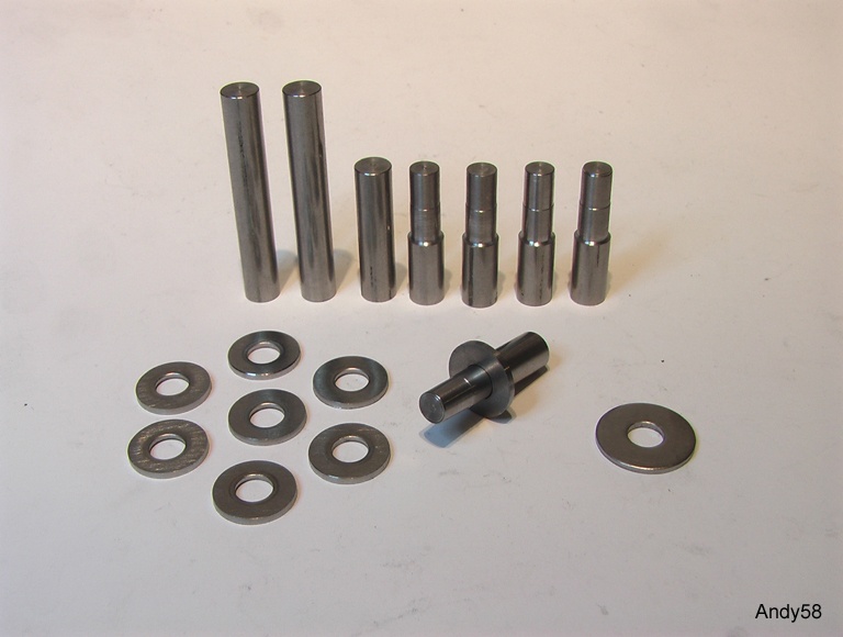
Figure 9: locking bolts and bearings
On the right is an unchanged washer (for metrical M8 screws) for comparison.
The top of locking bolt has to be flat, thickness is half of diameter. This is done in
the milling machine (figure 10).
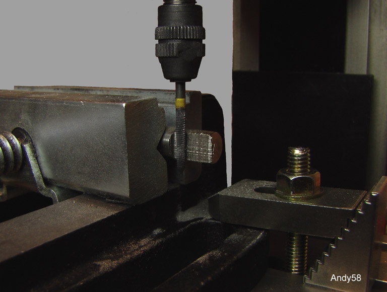
Figure 10: milling top of locking bolt
On the bottom of locking bolt is a 7mm slot to connect it to the Abloy cam lock. First i
have used a cut-off wheel sold for Dremel etc. But it is used in milling machine, so cuts
for sides of slot are much more precise (figure 11). Rest of material was milled away.
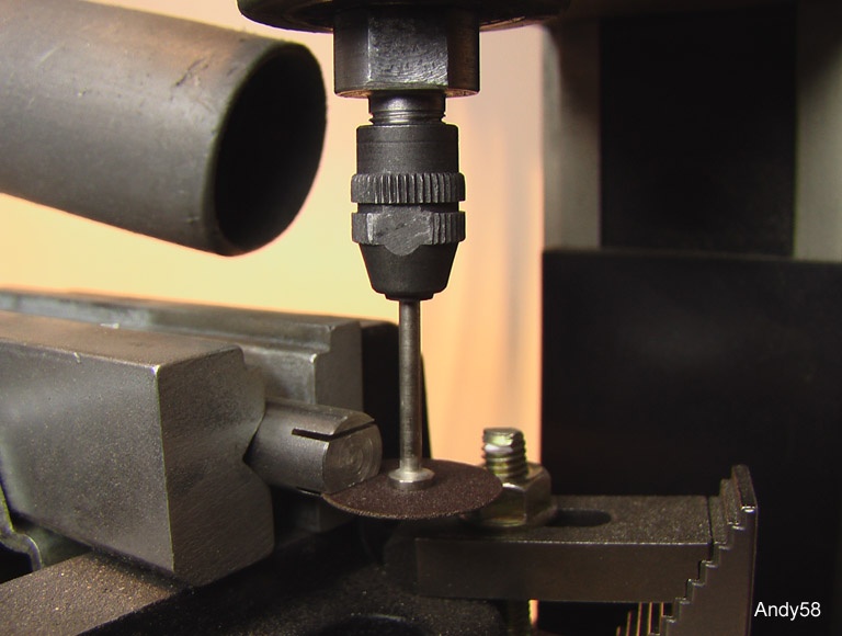
Figure 11: cutting slot of locking bolt
Abloy locks have a square ended thread. A hole has to be drilled into this end, also on both
sides of slot in locking bolts. But the square end of cam lock is too short, so i had to reduce
thickness of nut of cam lock (you can see original nut on
figure 2).
After doing this, Abloy cam lock and locking bolt can be assembled together (figure 12):
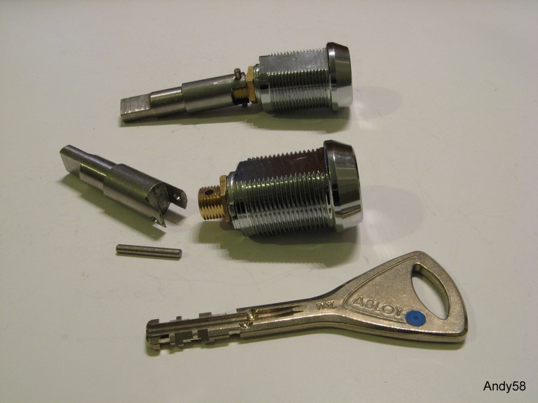
Figure12: lock assembly
Finally a little pin has to be inserted in the side of locking bolt. It inhibits extraction of
locking mechanism when lock is closed. Because welding is not so precise i have to wait until
all parts are welded together, then i can determine the exact position of this little pin. But
this is done later.
Inside lock body near hinge is a tiny lock holder inhibiting rotating cam lock. It has a thread
for a grub screw holding cam lock when it is unlocked. Figure 13 shows thread cutting and some
other already made lock holders.
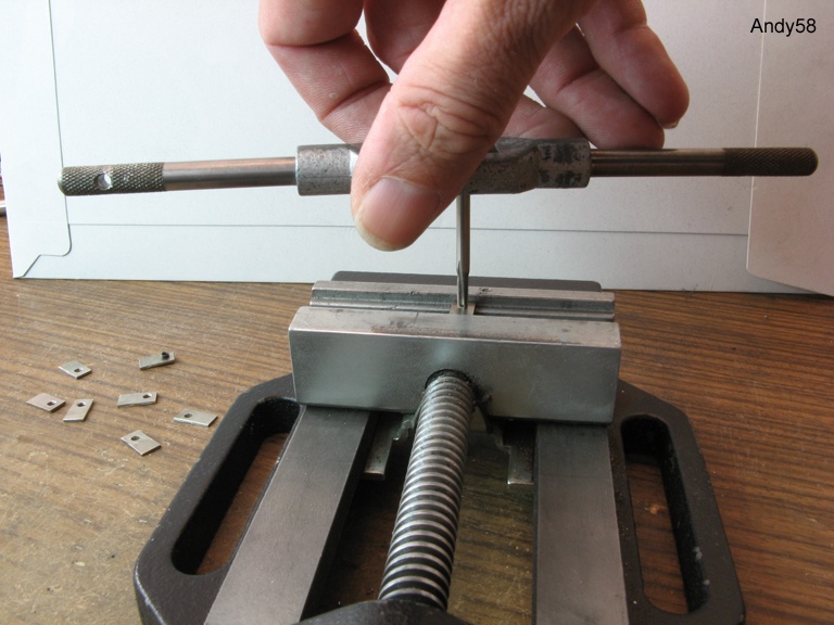
Figure 13: thread cutting for lock holders
On figure 14 you can see how lock is assembled inside lock body. The tiny lock holder is inserted
inside tube so grub screw fits through the hole. Cam lock is fixed by screw when it is open. Cam
lock and locking bolt are connected by a 1.4mm nail made of weak steel, so it can be bent to
prevent sliding out. This nail is strong enough to hold lock in place when locked but screw is
removed (see later).
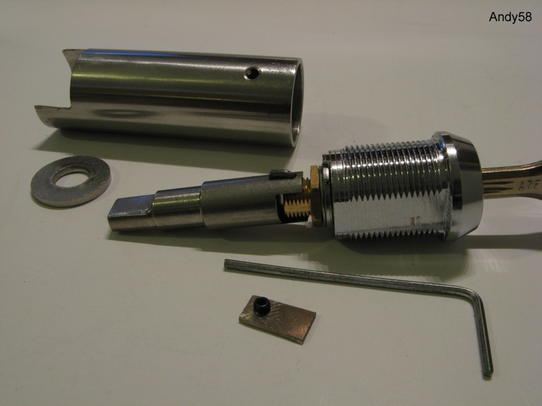
Figure 14: lock mounting
This locking mechanism has no springs, there is no snap shut. It is "positive locking" like
Chubb Escort.
Lock has to be closed by key, key is removable only in locked position. I have kept locking
mechanism simple (just a turning locking bolt), so there are less possibilities to manipulate
it. Shimming or rapping open is impossible, you have to open the lock (happy picking for an
Abloy Protec cam lock) or you must destroy bow or lock body. Bow is 20mm*5mm of stainless
steel, tube has 1.5mm wall thickness. Cutting hinge is a little bit easier, about twice
5mm*5mm, but bow will still be held by locking bolt on the other side.
[previous]
[1]
[2]
3
[4]
[5]
[6]
[next]